| Kevin's Compound Sequential Twin Turbo Design | ||
|---|---|---|
|
I've been thinking of doing a sequential turbo setup for a while now as a means of getting more boost at lower rpm, so that I can run a lower stall in my TH400 converter. A lower stall will allow me to have a converter that holds more power and has less converter slippage, which results in more power to the rear wheels. Having looked at every compound, sequential, and twin turbo setup that I could find on the net, there wasn't one of them that I was happy to install in my own car due to various fitment, cost and complexity reasons. Therefore I decided to design my own sequential turbo system. What I have come up with is, I believe far simplier, faster spooling and easier to control then any other sequential setup that I've seen. They say a picture is worth a thousand words, so here's a diagram of how it works. 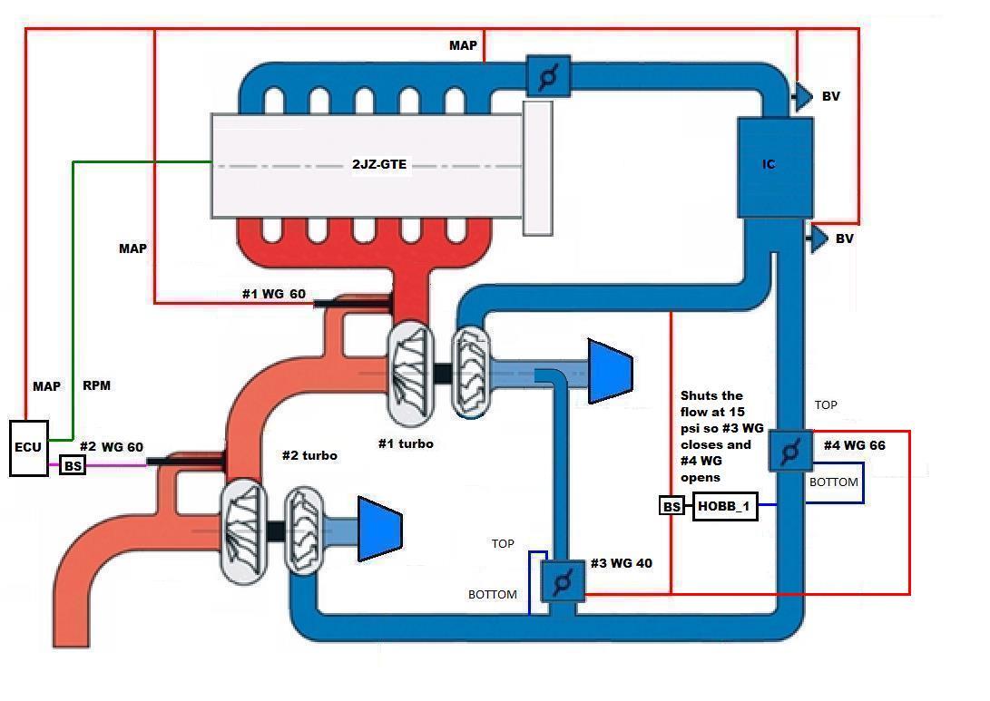
MAP = Manifold Absolute Pressure BS = Boost Solonoid RPM = Revs Per Minute ECU = Electronic Control Unit WG = Wastegate (number denotes size in mm) This sequential setup is basically a compound turbo setup on the exhaust side and a parallel sequential setup on the intake side. This means you get all the advantages of a compound turbo setup for spooling the turbos, but with none of the disadvantages of the compound setup such as the boost being too high for a gas engine. By spooling the second turbo with the gas exiting from the first turbo, the second turbo will spool much quicker then if it was just recieving some exhaust gas diverted from going through the first turbo, as most other sequential turbo systems do. This means it should be able to spool the second turbo quicker and instead of having a big dip in the torque curve when the second turbo comes on-line, there should be little to no dip in the torque, resulting in a torque curve more like a large single turbo. This setup is simplier then any other sequential turbo setup I've seen. There are two turbo control wastegates, one used for each turbo. The first turbos wastegate uses spring pressure only to control it. The second turbos wastegate will be controlled via MAP and RPM using the ECU. There are also two wastegates for controlling the compressor flow. These act as an Intake Air Bypass Valve and as a One Way Valve and work together to control the merging of the flow of compressed air from the #2 turbo in to the intercooler. The #4 WG lets flow from the #2 turbo through to the engine (like a One Way Valve) while the engine is under manifold vacuum as it cracks open with a 1 psi pressure difference. When the manifold pressure reaches zero psi boost, the #4 WG automatically closes. When the #1 turbo pressure reaches 2 psi boost, the #3 wastegate (used as an Intake Air Bypass Valve) opens against the 2 psi spring installed in it. This lets flow from the #2 turbo vent to the #1 turbo intake pipe. When the #2 turbo pressure reaches within 2 psi of the #1 turbo, the #3 wastegate closes and the #4 WG automatically opens which allows boost from the #2 turbo to go to the engine. When boost from the #2 turbo drops below that of the #1 turbo by 2 psi, the #4 WG automatically closes and the #3 wastegate automatically opens, which resets it for the next cycle. My design uses a SPA manifold to keep it compact. 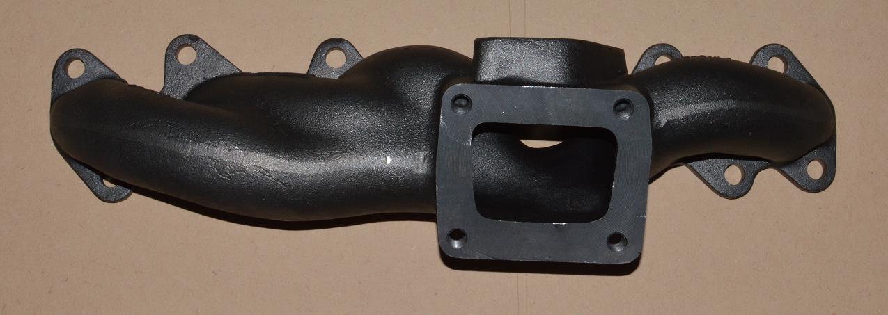
Here's a drawing I did to show how my sequential setup will be implemented in practice on my 2JZ-GTE Supra engine. 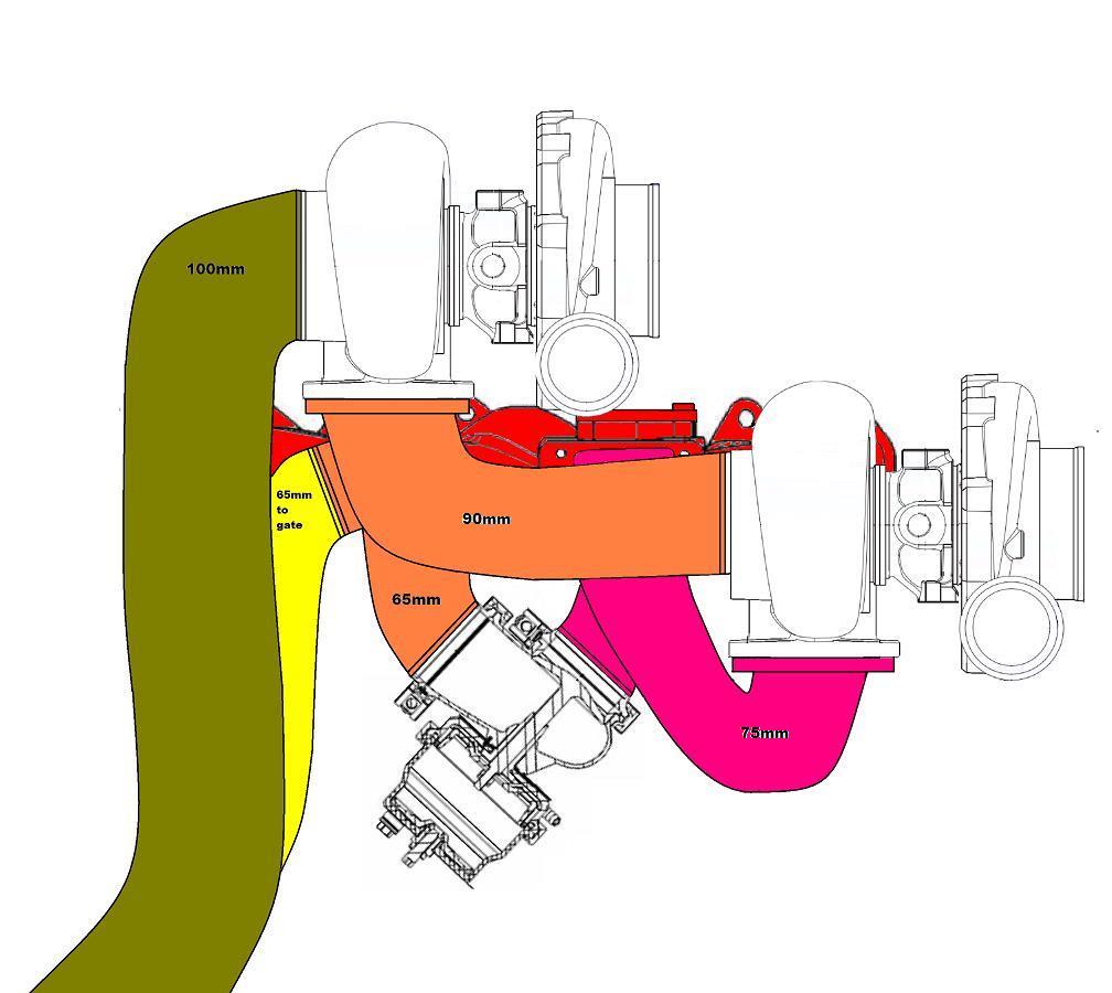
My design uses a 3.5" down pipe between the #1 and #2 turbo, a 4.0" down pipe for the #2 turbo. The first wastegate is a new Turbosmart 60 wastegate to get maximum flow bypassing the first turbo. The second wastegate (not shown in the pic above, but resides at the bottom left of the pic behind the down pipe) is my existing Turbosmart 60mm wastegate.
Here is how the system should work:
I've started the fabrication on my sequential setup, so here are a few pics of whats been done so far. 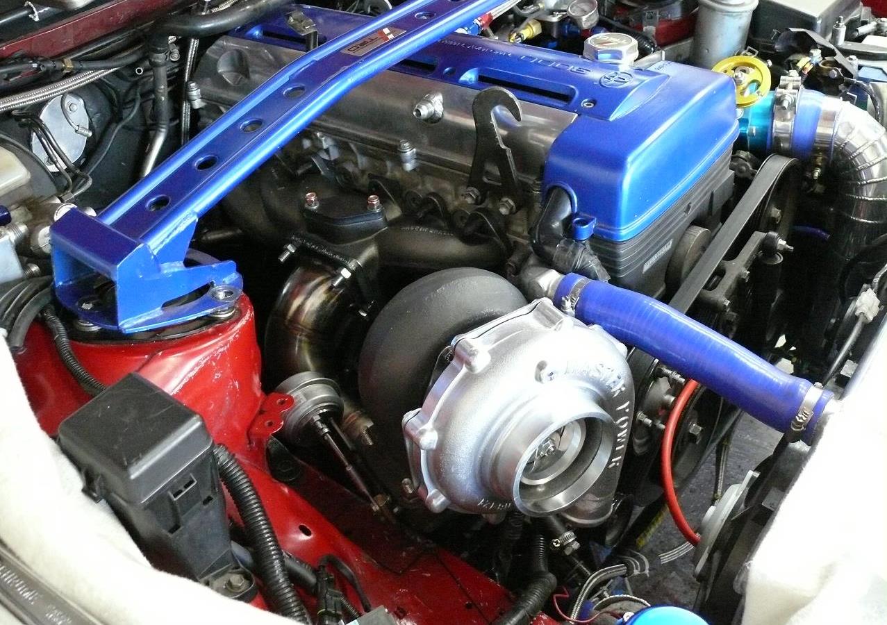 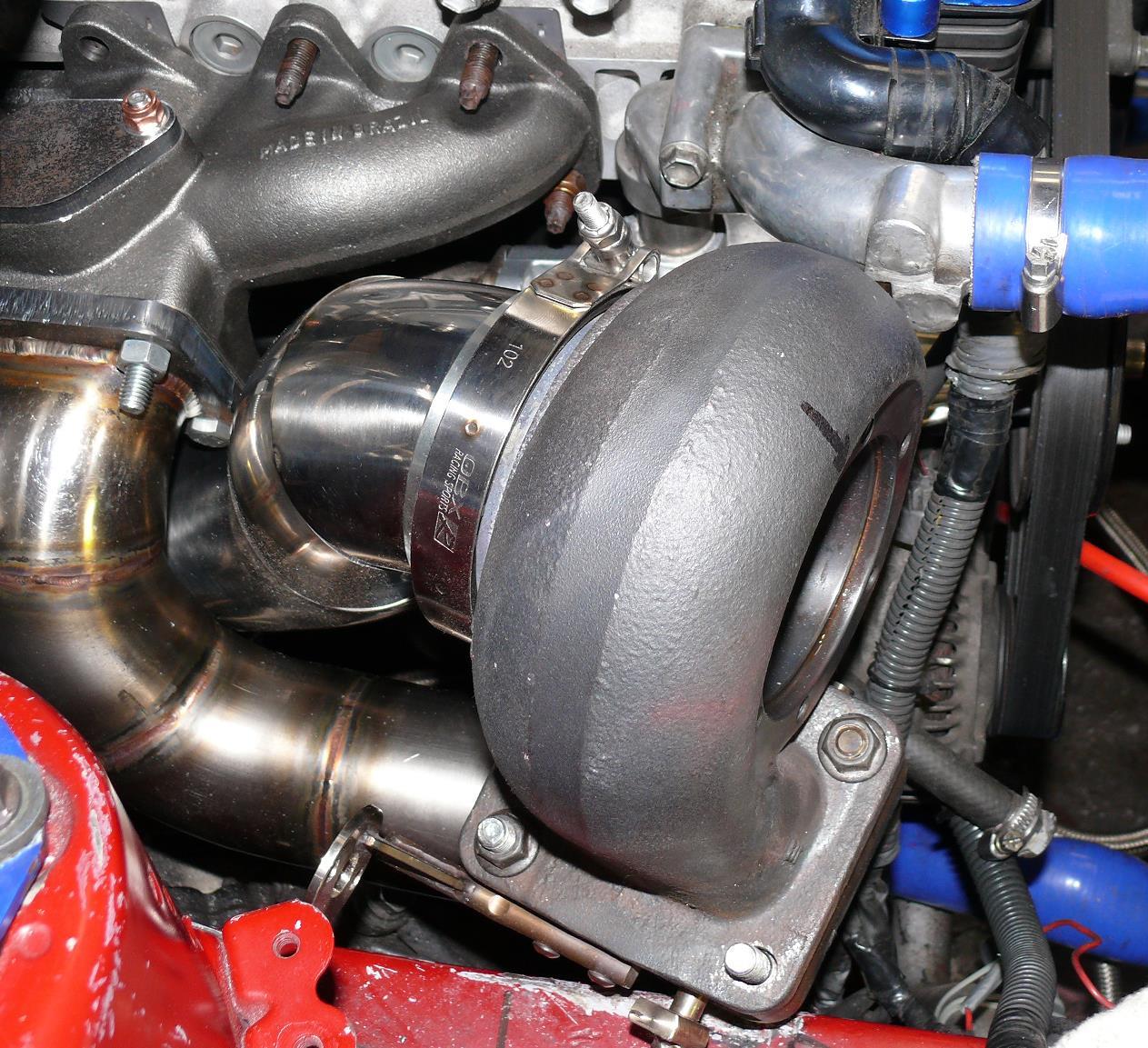 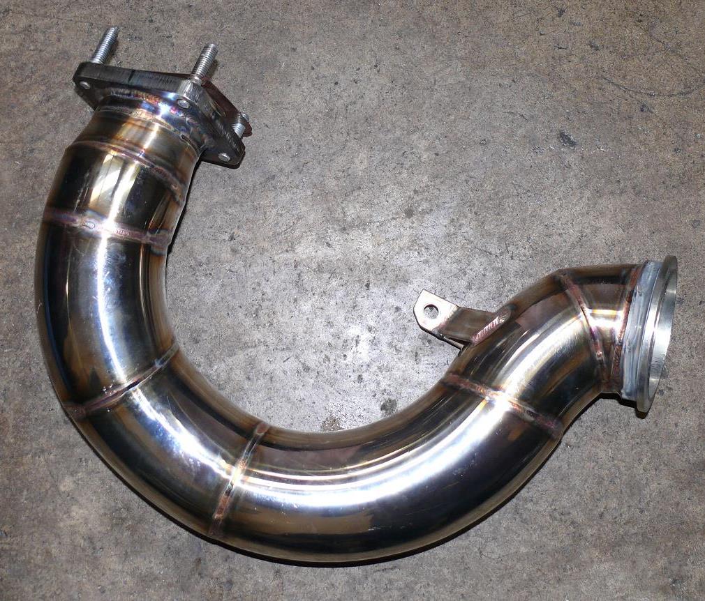 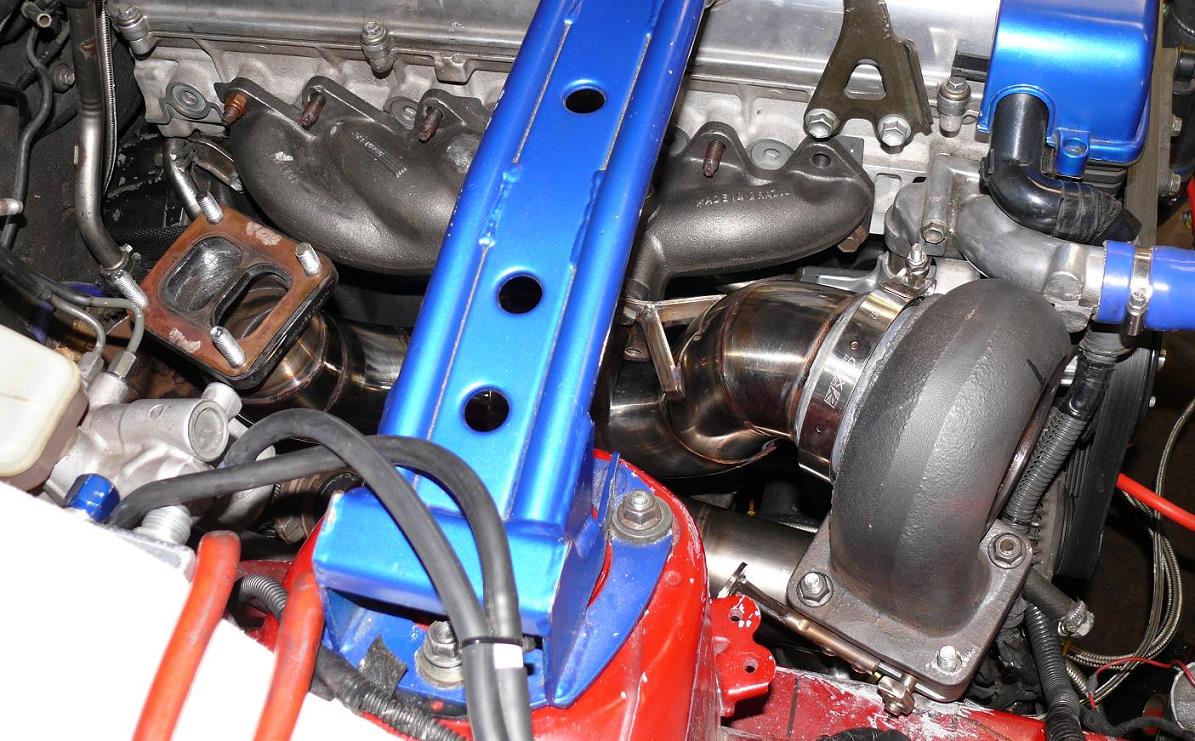 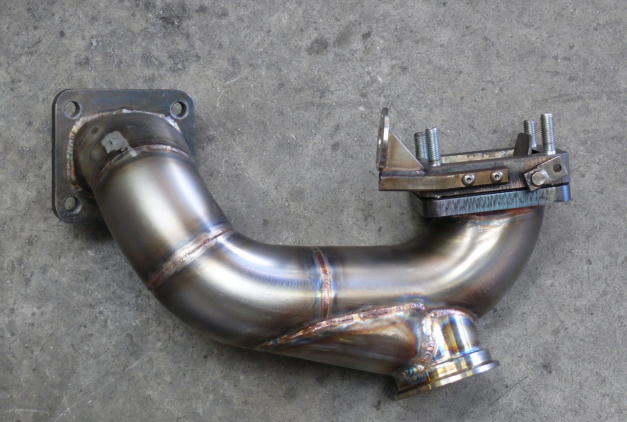 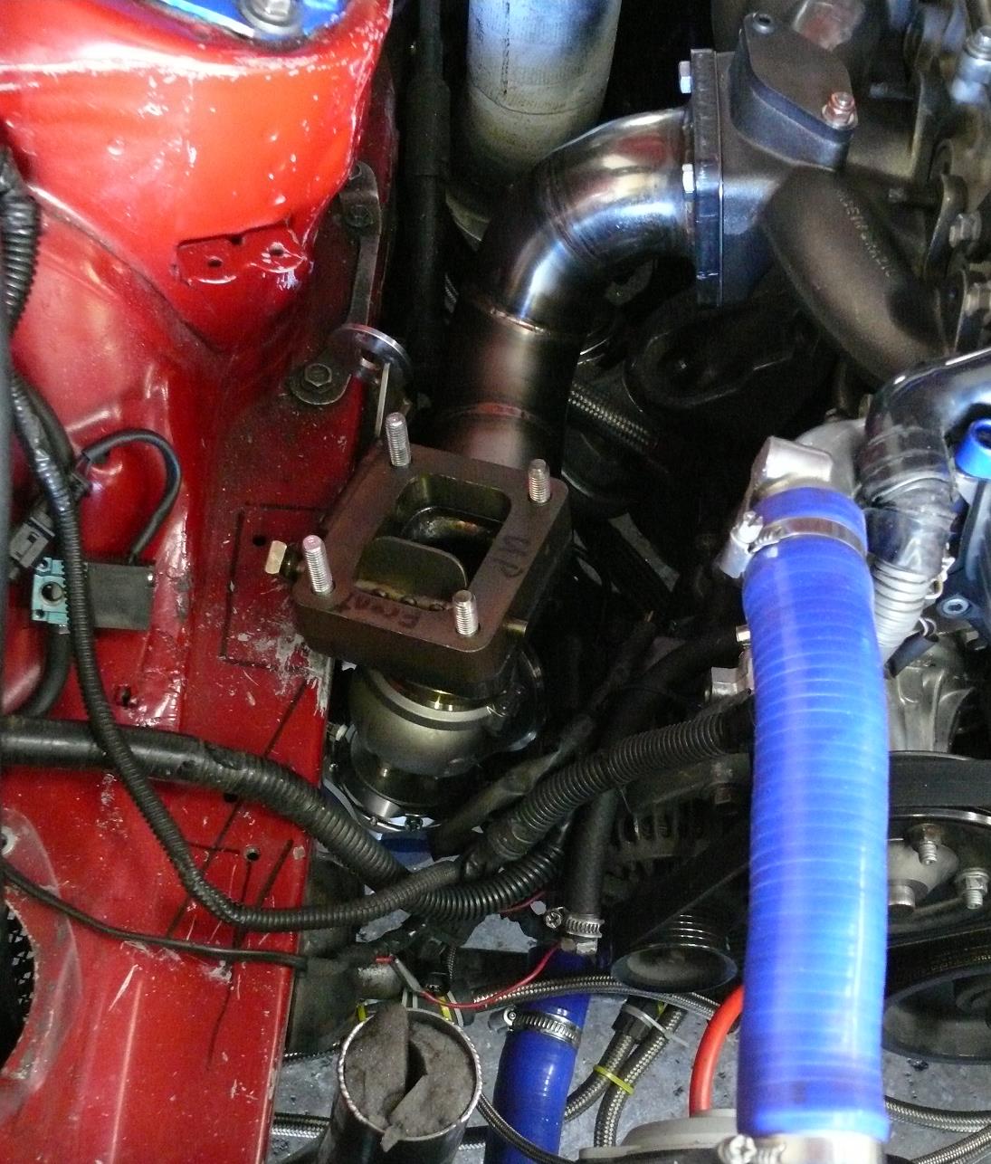 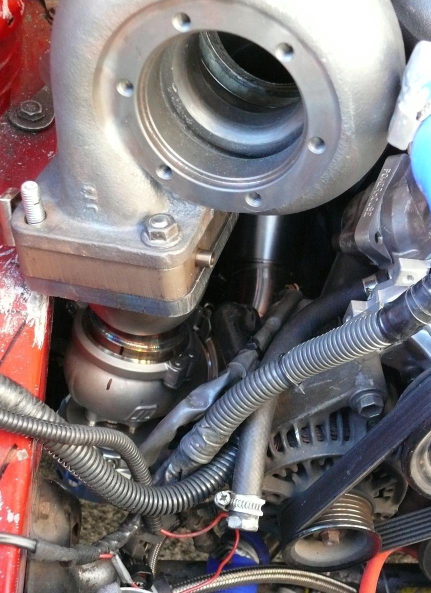 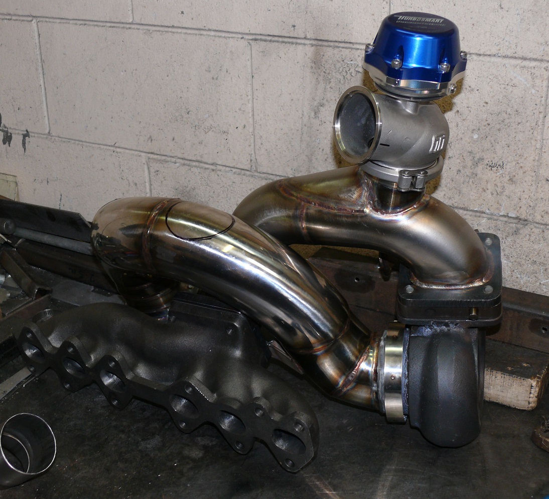 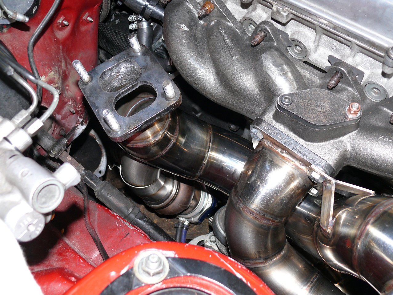 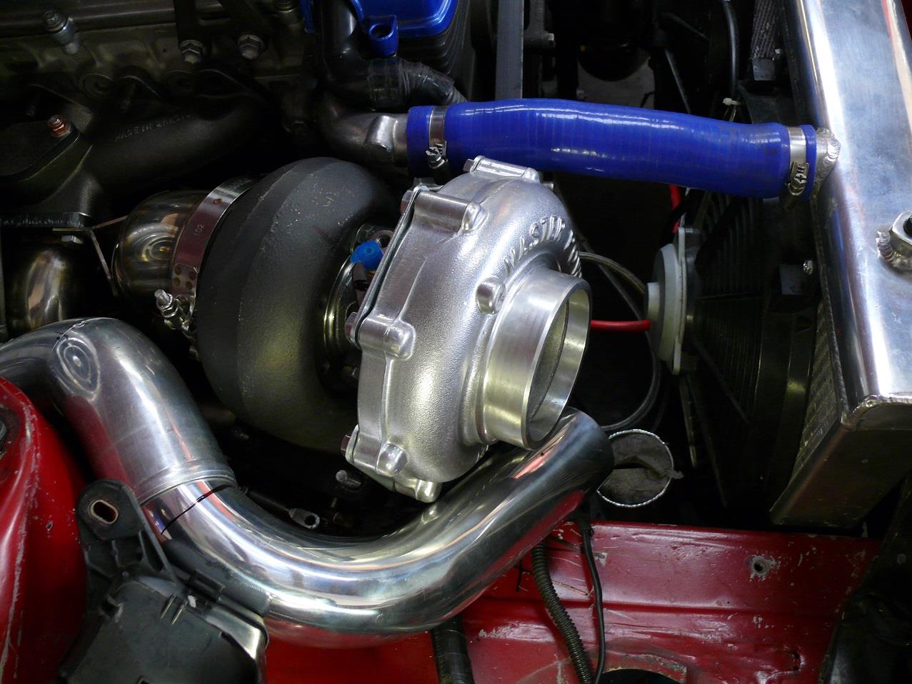 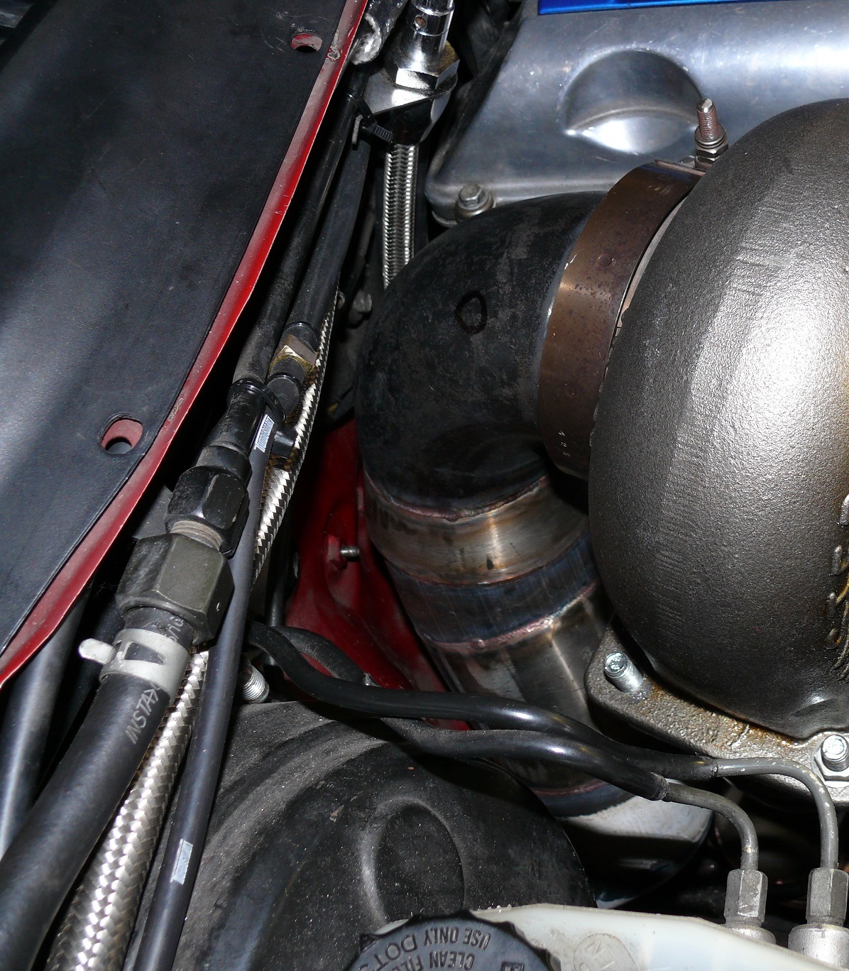 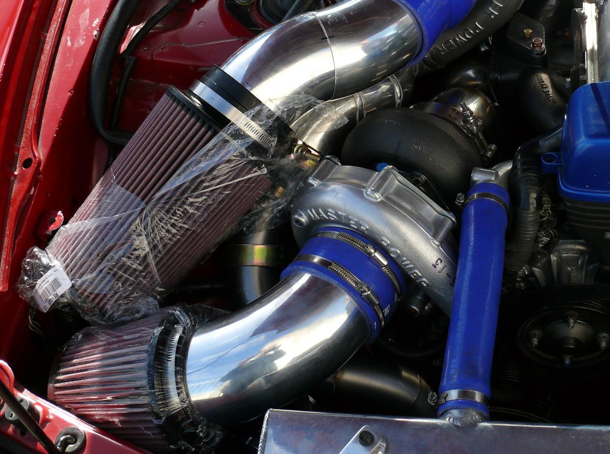 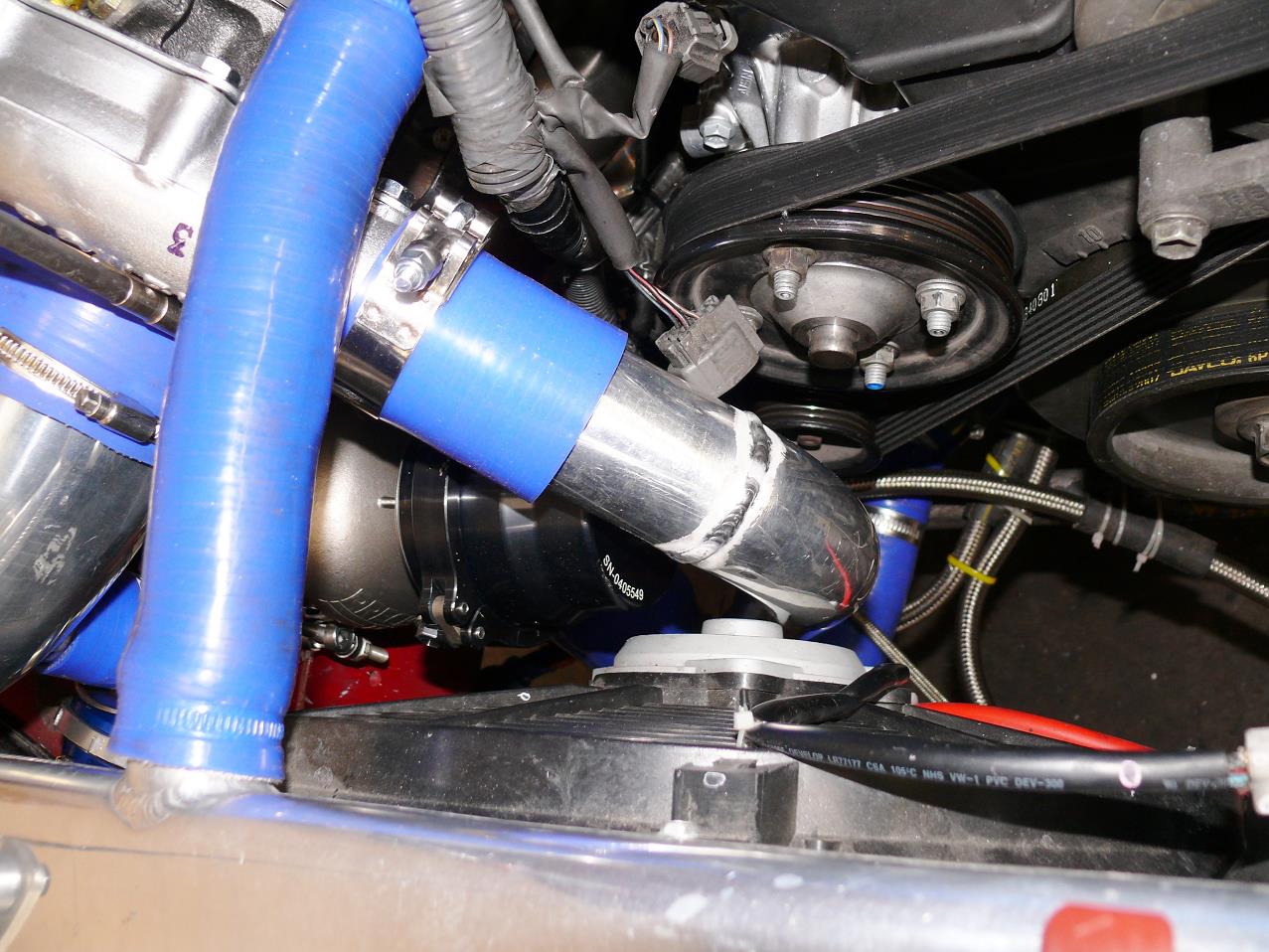 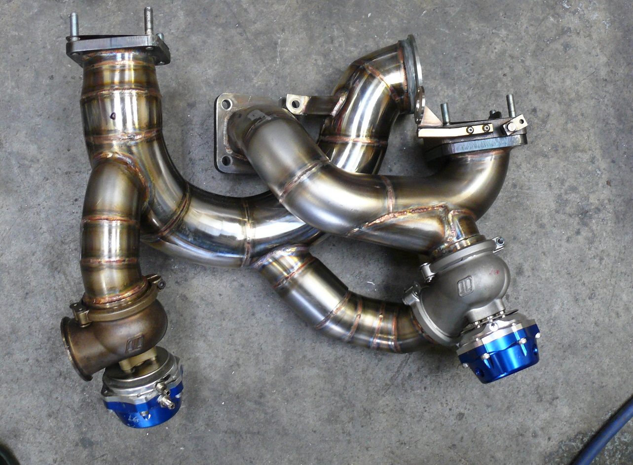 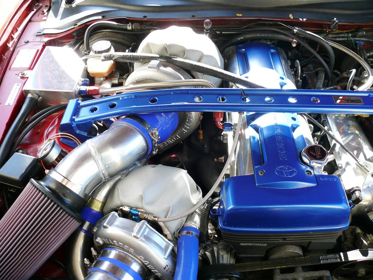 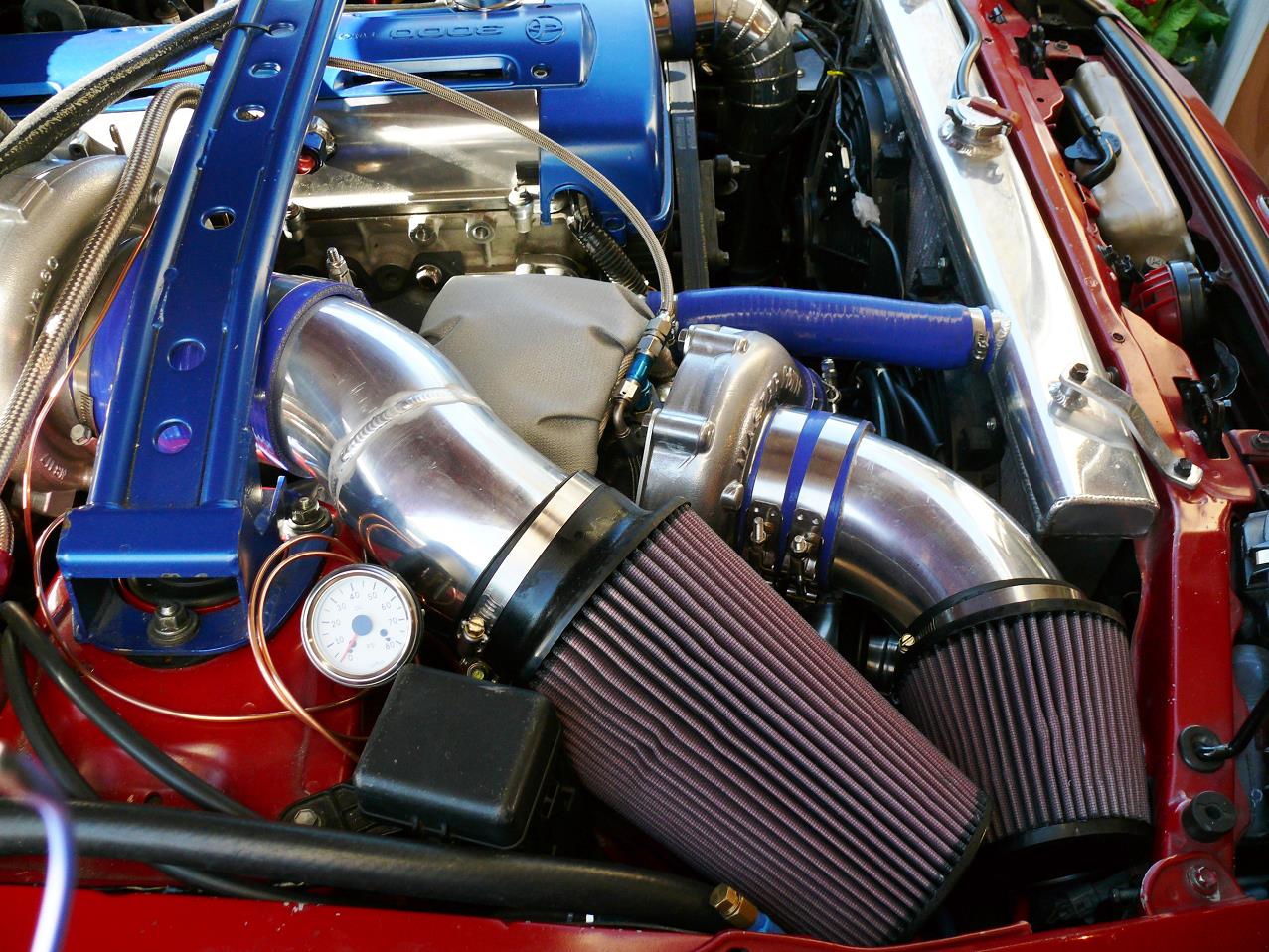 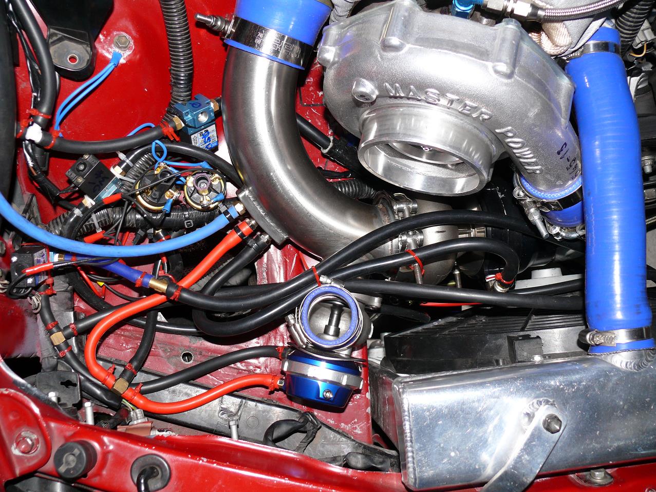 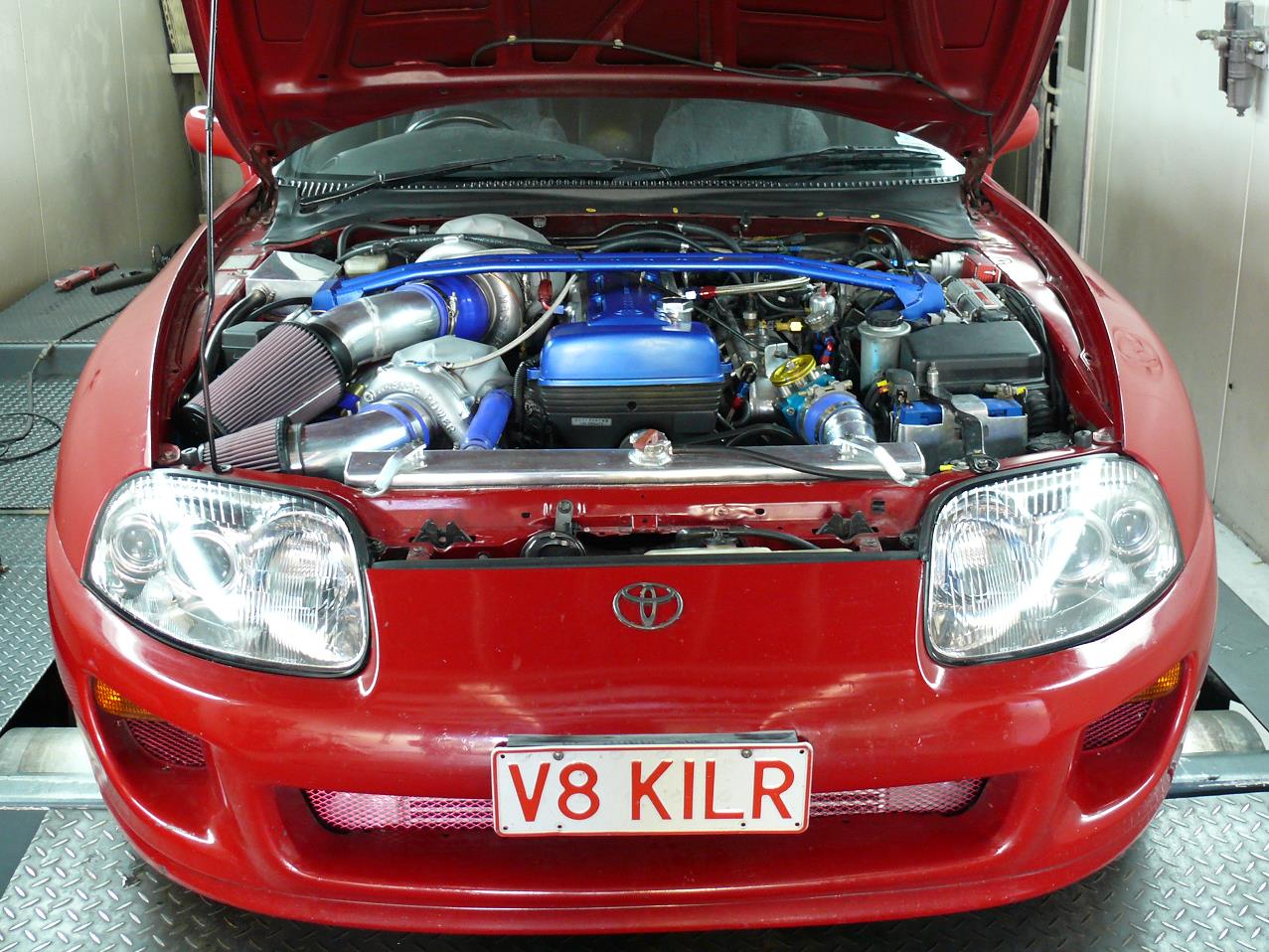 The sequential setup wasn't spooling fast enough so I have converted it to a true compound setup. The blue boost line in the dyno sheet shows how much quicker it spools compared to my T70 single turbo setup. Unfortunately it was making so much torque at much lower rpm that it over powered my converter. 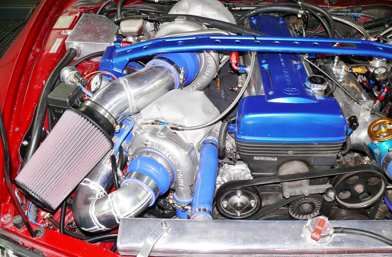  I've decided to pull the TH400 out and put my Getrag V161 back in the car. Testing on the street with the compound setup, it still doesn't launch as hard as I want it to with the auto and nowhere near as hard as it used to launch when I was manual. Unfortunately this means the compound setup is coming out. Despite showing great promise for spool, the rear down pipe doesn't leave any room for the clutch master cylinder where it bolts to the firewall. I'll be going back to a small single turbo setup (probably a MasterPower 6564) bolting on to the SPA manifold (to keep it simple), and with E85 it should still make pretty good power. There were still some issues with the compound setup with oil drain leaks and the big issue was that the thin wall stainless pipes were getting red hot with just one dyno run and the associated heat issues that can cause. Both are fixable, but not easily so and made harder by needing to allow for the clutch master cylinder. | ||
Thanks for visiting mkiv.co.nz
Last modified on Sunday 9th November, 2014