| Kevin's Divided Manifold Quick Spool Valve | ||
|---|---|---|
|
If you have a manual Supra, I don't see much need for a Quick Spool Valve (QSV) as you can either change to a lower gear or dump the clutch at higher rpm to launch. However last year I changed to running a TH400 and launching the car quickly has now become an issue. No one seems to be able to make a decent high stall converter so that leaves a QSV as one of the few other options available, as I have no intention of running NOS. The Sound Performance QSV is not designed to work with a divided manifold and as I have an extremely well made 6Boost divided manifold, I did not want to modify it just to fit a QSV. I am also not convinced that it would be the best option to modify my divided manifold to an open manifold, just so I can use a QSV. Here is my 6Boost manifold merge chambers and as you can see they look like a very good design. 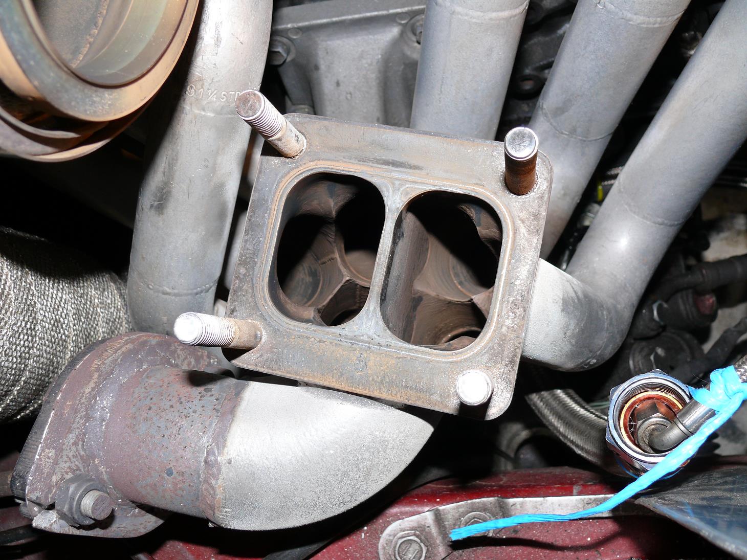
While doing some web searching, I came across the BD Turbine Diverter Valve which is an extremely good design and very well made, but at about 40-50mm (1.6-2.0") high, it is just too bulky for me to consider using in my Supra. This is because it would raise the turbo so high that I would no longer be able to use my TRD strut brace and if I change to a larger turbo, I would have bonnet clearance issues. 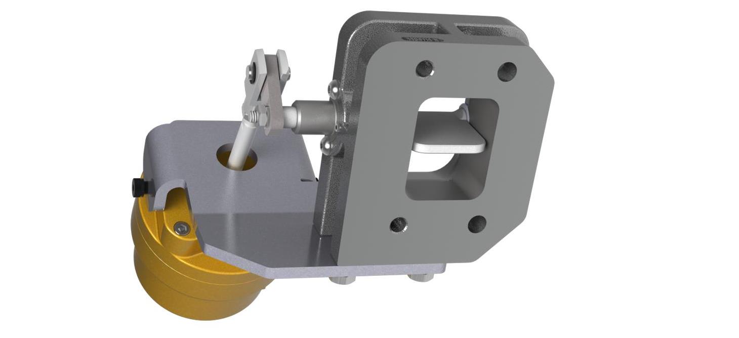
So what I did was design a QSV that works with an unmodified T4 divided (split pulse) manifold, which I got made locally in New Zealand. Here is what I came up with. Note that the two piece actuator shaft in some of the pics below was an earlier design that proved to be unreliable. 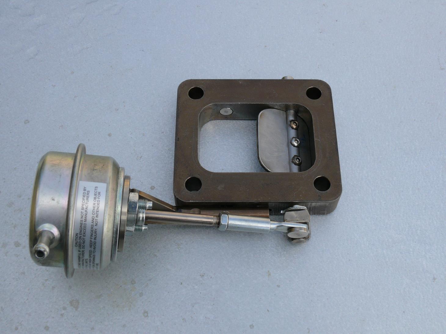
It uses a 20mm (0.8”) high undivided flange as the body of the QSV. As it is missing the center divider in the flange, when the QSV is closed, the QSV butterfly redirects the exhaust gas to the other side of the divided turbo inlet. The butterfly is also slightly wider than a standard QSV butterfly so that it can make a closer seal against the bottom of the turbo center divider and offer a more gradual flow angle for the exhaust gases to the other turbo inlet. 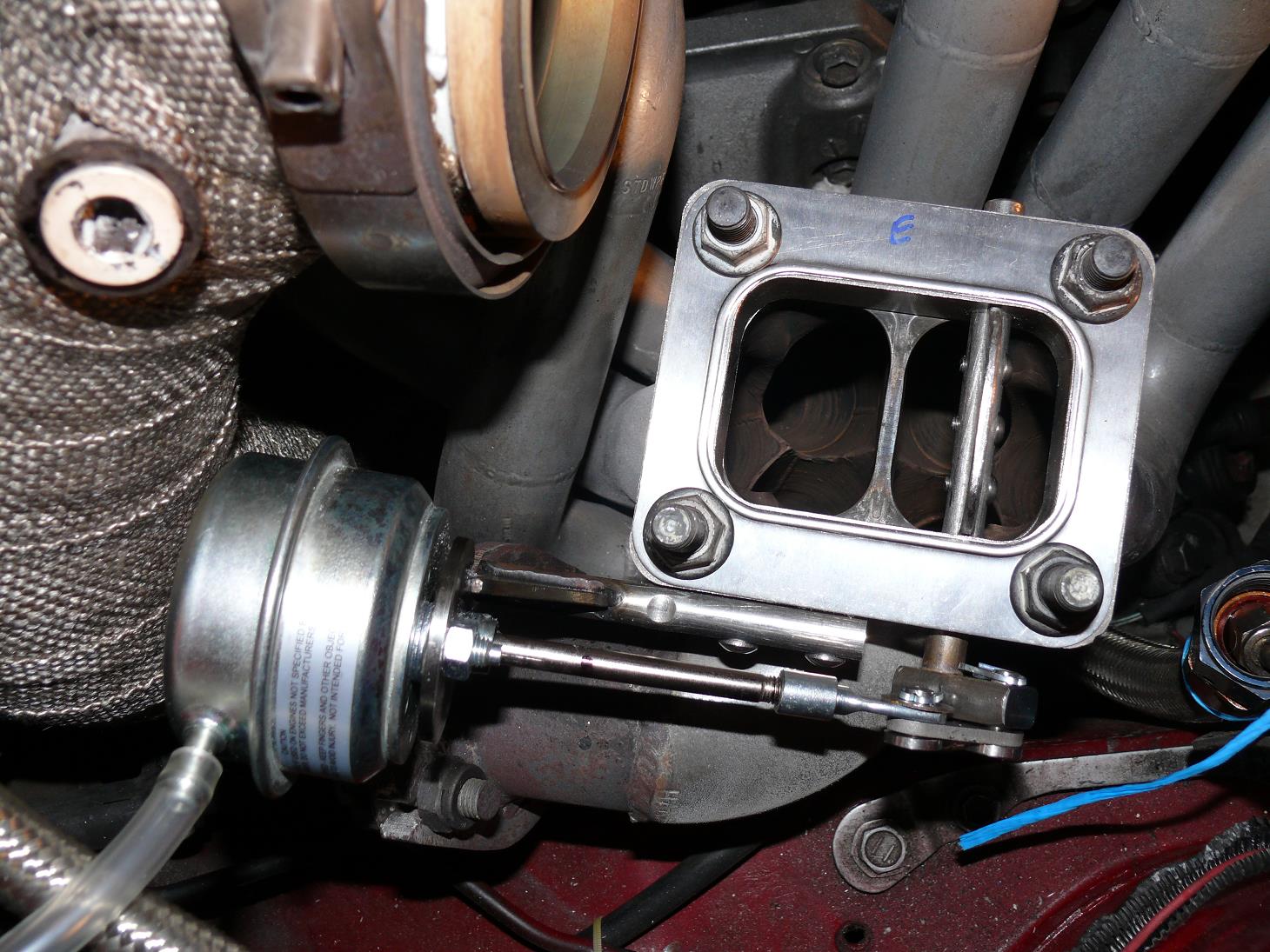 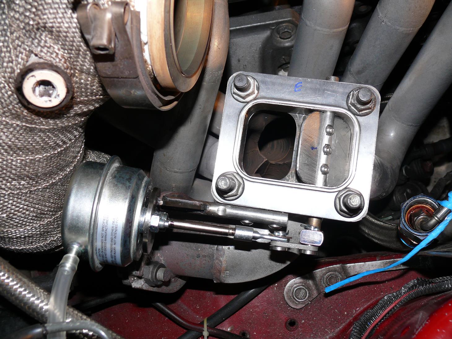
After starting building this one, I found several home made ones for divided manifolds that are very similar and were used on diesel engines. One was 1.25" thick and the other was 1.5" thick and both were said to work very well. As diesels engines produce more exhaust gas then petrol engines do, a slimmer design for gas cars should work. This does mean that the exhaust gas from one side of the divided manifold only has a maximum of a 20mm high space to flow through to get to the other side. As the T4 flange has 36-37mm wide entry ports, this allows around 55% of the area to flow the exhaust gas through compared to when it is open. As we eventually squeeze the exhaust gas by 50% when all the gas goes through one turbo volute anyway, I don’t see this as an issue. As the QSV parts will be subjected to very high temperatures using this exhaust gas flow redirecting method, the shaft and butterfly are both made from stainless steel. Here you can see the 20mm gap that the exhaust gas flows through to get to the opposite volute. 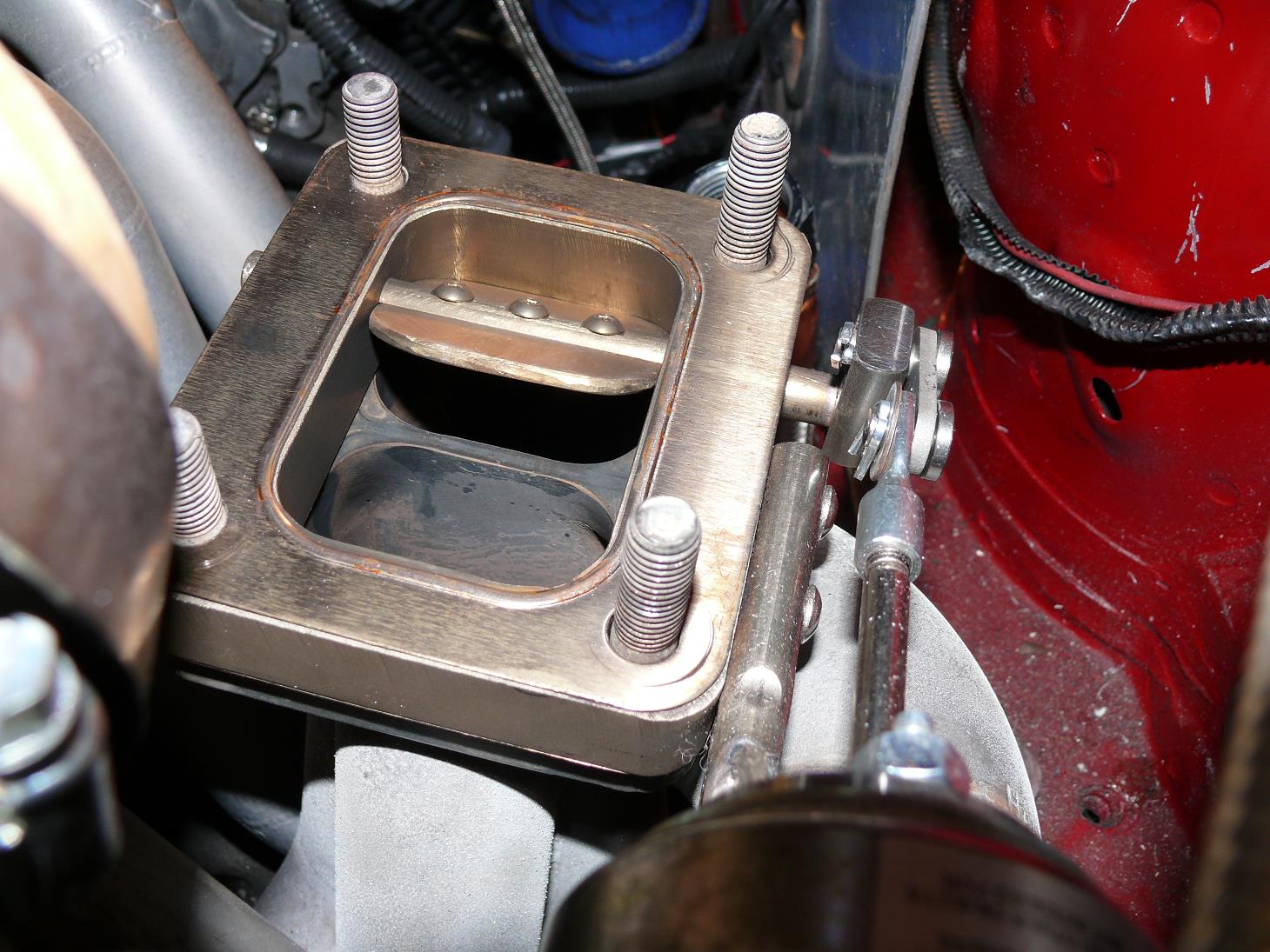
The exhaust gas does need to make a sharp turn as it enters the open port on the turbo which will introduce some turbulence where the two exhaust flows join, which will probably increase back pressure and slow down the gas flow. This could potentially cause too much restriction on the 3 cylinders (cylinders 1-3 in my setup) feeding the QSV. One reason why there should not be too much restriction from my QSV design is that my 6Boost manifold has a single 50mm wastegate pipe that connects to both of the divided sections of the manifold. The exhaust gas has no distance at all to travel down the wastegate pipe before it can flow around the separator and out the other divided tube in the manifold. This should allow both sides of the divided manifold to equalize the exhaust gas pressure to compensate for the QSV generating extra back pressure on one half of the manifold. Here is the wastegate ports on my 6Boost manifold. 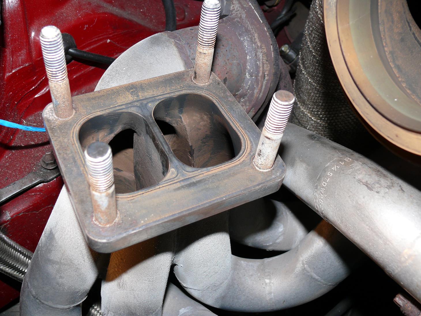
As the QSV will generate extra back pressure at all times including when it is fully open, this will then make more exhaust gas flow through the opposite volute which will effectively reduce the AR on that side. To compensate for the extra back pressure, I could change my turbine housing AR from my custom 0.84 divided housing to my original Masterpower 1.00 divided housing (a 19% increase in AR) if I find that max power has dropped. The actuator is a Garrett wastegate actuator that begins to open at 6 psi and is fully open by 11 psi. I did some test drives on the weekend with the QSV set closed and around 15 psi seemed to be the point where it would be good to have it opening by. I will install a hobbs switch and get the ECU to control the opening point to optimize the spool. Here is what the completed setup looks like. 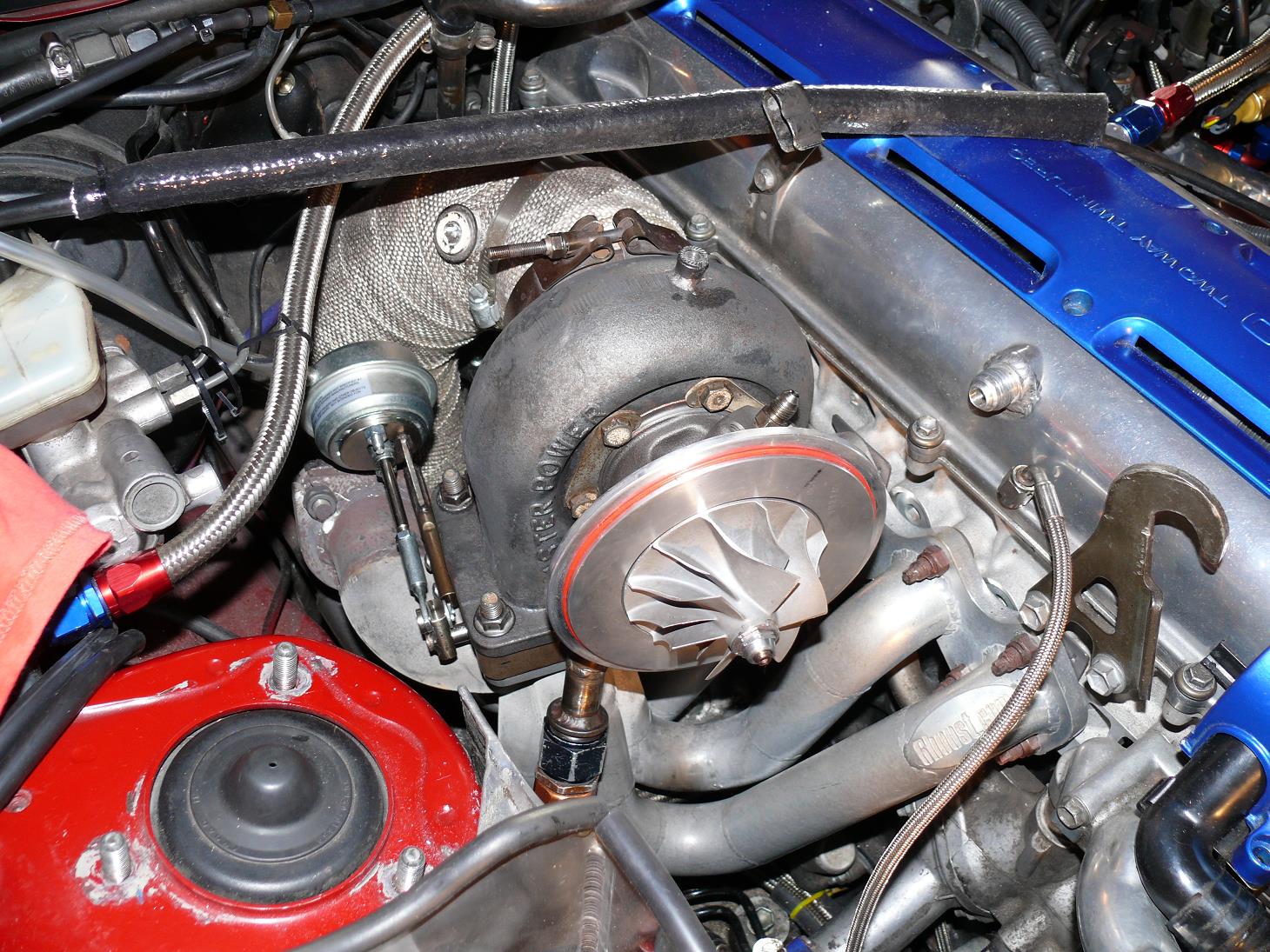
With my current 2600 rpm stall converter that I bought (despite asking for a 4200 rpm stall) I could not get the engine rpm to climb above 2600 rpm when foot braking it with the throttle wide open. After installing the QSV, I did the same test and the rpm went past 2600 rpm and continued climbing fairly quickly until I hit over 20 psi of boost about 5-6 seconds later with the QSV set closed. This is a HUGE improvement in spool. The proof of whether it works or not is in the testing, as it is with any QSV design. It is not easy to get exact dyno comparisons of before and after results, as dyno graph boost curves can vary considerably depending on exactly what rpm you start the run at, so the best option is actually to do data logging. So once I get the converter changed, I plan to time how long the foot brake stall takes to get from 2500 to 4500 rpm. I'll also log manifold pressure, TPS and RPM, so as to make for a valid comparision. In the mean while here is a dyno graph with the QSV in red. This dyno is for the 3000rpm converter which unfortunately slips more then the 2600rpm converter, resulting in the lower power line. I have calculated that the QSV reaches 25psi boost around 550rpm earlier (88kmh vs. 107kmh) despite starting the QSV dyno run at higher mph. 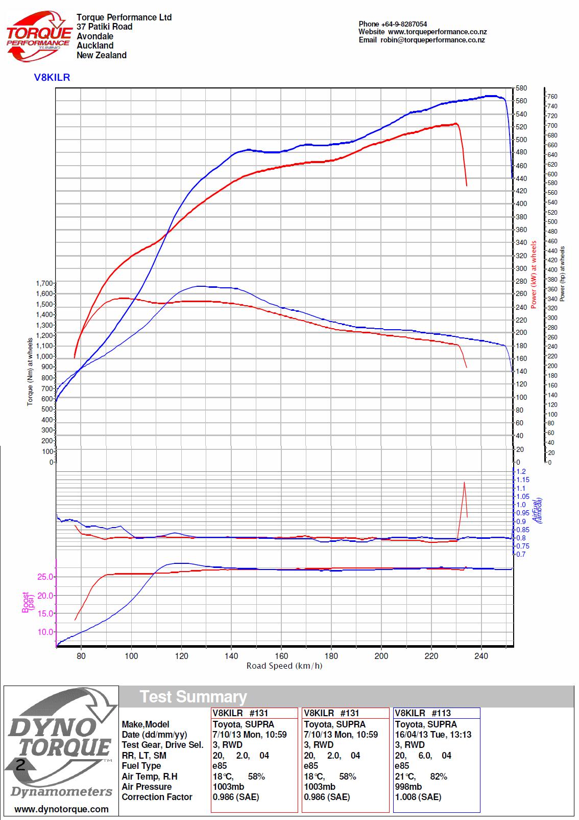
| ||
Thanks for visiting mkiv.co.nz
Last modified on Monday 7th October, 2013