| 550cc Injector Upgrade |
The Japanese mkiv Supra injectors are 430cc per minute injectors and at 80% duty cycle, they will run at about 55hp per injector or 330hp for all six injectors. The 80% duty cycle is the accepted industry standard because with injectors being solenoids, we want to avoid overheating the injectors as this will cause uneven or irregular response from the injectors. At 100% duty they will peak at 68hp each or 410hp for all six injectors. Also at high revs and high boost the injectors may not be able to deliver the required amount of fuel in the time available, even when running at 100% duty cycle. See the RC Fuel Injection article and the September 2000 Performance Car Issue #45 for the source of this information. Some mkiv owners are running their Japanese mkiv's TT's with more flywheel hp than this (equates to about 315 rwhp on Aussie/NZ dynos), so these calculations are obviously conservative. However, there will come a point where the std mkiv injectors cannot provide enough fuel to keep the fuel ratio sufficiently rich (about 11.5 - 12:1) for the high boost required to produce these hp figures on standard turbos. From the hp figures some of the group members have achieved and their fueling under those conditions, I would say any more then around 330-340rwhp will very likely result in lean conditions under high boost. A very old saying "better safe than sorry" is the best attitude to adopt, as the mkiv motors are not indestructable. I know of at least one mkiv in Aussie that destroyed itself at 22psi boost, and I have destroyed several spark plugs when I had runaway boost to 25+psi. Note: Please read all the following instructions carefully and completely before starting. This information is provided on the basis that it is as complete and accurate as possible, but remember, you and you alone are responsible for any modifications that you perform on your vehicles. If you do not have the necessary knowledge to perform these modifications yourself, then pay for an experienced automotive engineer to do them for you. This information has kindly been provided courtesy of Lindsay in Christchurch, New Zealand who has already modified his Japanese mkiv TT to use the larger 550cc Export injectors. His purpose was to help eliminate the possibilty of detonation occuring under high boost conditions and to avoid running near 100% duty cycle on the std 430cc injectors.  Electrical differences:
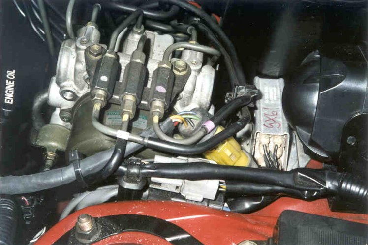
Japanese injector wiring diagram showing the wires for injectors 2-6 coming from the harness at the rear of the car and the wire for injector 1 coming from the harness where it goes behind and under the cam cover. 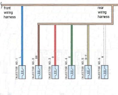 After adding the EFI Resistor (as per the USA mkiv's) the injector wires now all come from the harness at the rear of the car as the old wire to the no. 1 injector has now been rerouted to the EFI Resistor. 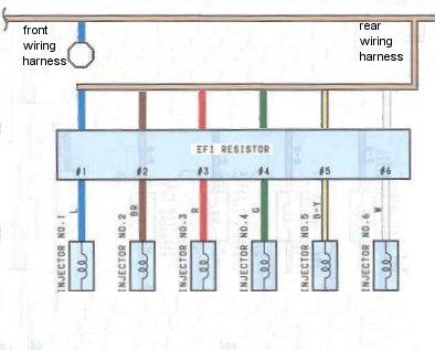
 Instructions:
Lindsay changed over to the 550cc injectors on his mkiv, in conjunction with changing the inlet cam for an Export spec one. He also removed the viscous fan and replaced it with a 16" electric fan. 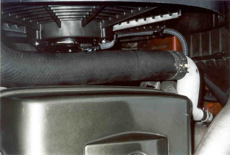 See the dyno sheet below that show the hp changes as a result of these modifications. The dotted line (341.9rwhp) is the before and the solid line (357.4rwhp) is the after, an increase of 15.5 hp (4.5%). As you can see all the extra power is after 4500rpm, and is mainly due to the export inlet cam. The bigger injectors don't give any more power (probably a little less on Lindsay's as it's running too rich at the moment) and the 16" fan only gives a saving when the fan is actually running. Peak torque has improved a little more with an increase from 308.3ft/lb to 328.4ft/lb (6.5%). 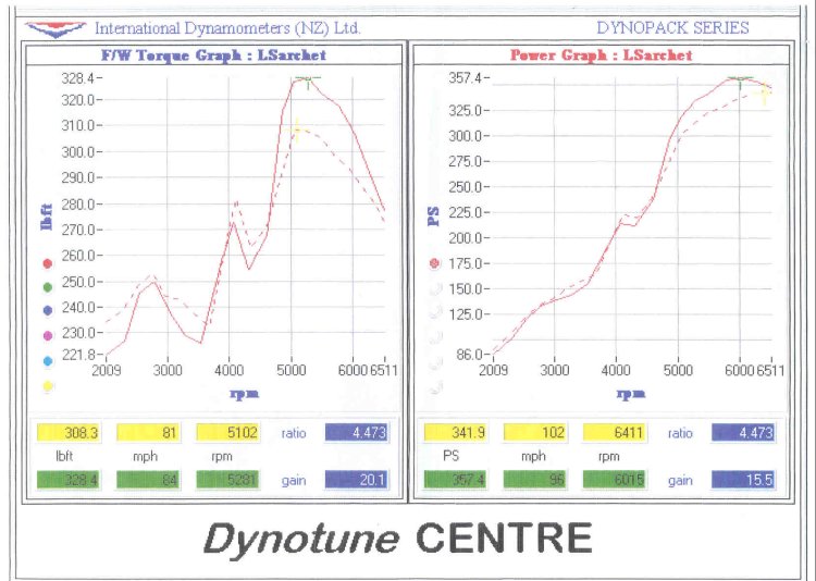 The oxygen sensor information is only used by the ECU in learn mode, which runs up to around 5000rpm, so changing to the 550cc injectors will make it run a bit rich at the top end, even after the ECU has done its learning. The export inlet cam allows for about 5% more airflow at the top end, so helps compensate for the extra fueling to a certain degree. Here's the calc. 550 / 430 = 1.28 / 1.05 = 1.22. So it's still running around 22% rich. The ECU may be smart enough to not run quite this rich, but based on Lindsay's CO readings, it still runs too rich at high revs. How can I fix this? You can alter the MAP sensor signal by use of variable potentiometers to trick the ECU into supplying less fuel at the top end. You could make this yourself (see Autospeed DIY Injectors article) or buy an item such as the flowmate fuel controller that allows you to adjust the MAP sensor signal, before it reaches the ECU. This should then allow the original fuel economy to be largely maintained. Most fuel cut devices also alter the MAP sensor signal to eliminate the fuel cut that occurs at around 15-16psi on the mkiv Supra. You cannot run them both at the same time as they both usually plug into the ECU at the same place. NB: Blowing-up an engine (especially a turbo one) developing a heap of power is as easy as one power run with lean mixtures. Mixtures should be monitored by an air/fuel ratio meter. Doing this with the car on a dyno gives the best control over what is happening. Start off rich and then lean things out - don't go the other way. When adjusting the MAP sensor signal to the ECU, first disconnect the oxygen sensor, otherwise the ECU will be trying to learn while you are altering the MAP sensor signals to the ECU. Concentrate on getting the high loads right first (5000-7000rpm), rather than the light loads. However, when the mixtures are set perfectly for high load conditions, then they may not be right at light loads because of non-linearity in the engine's fuel needs when compared with its unmodified state. If the light loads look a bit too rich (or lean for that matter), don't worry; when the oxygen sensor is re-connected they'll lean (or richen) as the ECU learns its new mixtures. 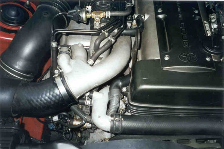 What about the fuel cut that occurs at 15-16psi? If you reduced the MAP sensor signal by say 15%, then just using the flowmate (or the homemade device) alone, would increase fuel cut from 15-16psi boost (30-31psi absolute) to around 20-21psi boost (35-36psi absolute) which is higher then the max boost you would want to run anyway.  Any questions or comments, then please email Lindsay |
|---|
Back to Home Page
Thanks for visiting mkiv.co.nz